Posts

Chess for Android v5.4: Adjudication

Image
I am rolling out Chess for Android version 5.4 on Google Play . Besides minor improvements, the major new feature consists of draw and resign adjudication during chess engines tournaments. As shown below, a new tournament dialog has been implemented which shows, besides familiar older options, a section for draw and resign adjudication. If during a game, after the given move number and during the given move count, the score drops below the requested draw score (in cp) or exceeds the requested resign score (in cp, either consistently for white or for black), the game is adjudicated rather than played in full. This feature has been requested many times by tournament managers to avoid wasting time playing e.g. boring drawn games until the 50-move rule applies. See this talkchess posting for an example game. As usual, let me know if you encounter problems with the new release. Also, I could use some help translating the new strings into several languages (most will display Eng...

Micro-KIM Tutorial: The Memory Map

Image
Let’s revisit the Micro-KIM memory map, introduced in the third tutorial. +-----------+ | 2K EPROM  |$1fff | monitor   | | program   |$1800 +-----------+ | 6532 RIOT |$17ff | I/O, timer| | and RAM   |$1740 +-----------+ | optional  |$173f | I/O, timer| | and RAM   |$1400 +-----------+ |           |$13ff | 5K RAM    | |           |$0000 +-----------+ Since the default kit (without any expansion) only uses the lower address bits to access 8K, memory repeats itself every 8K. You can verify this by storing and inspecting values in, for instance, addresses $0000 and $2000. Any value stored in one address will show up in the other. Although an interesting factoid, there is no reason to let Micro-KIM programs address anything outside the range $0000-$1fff. Addresses $0000-$13ff contain 5K free RAM (another interesting factoid: the Micro-KIM actually wastes 3K of its 8K RAM chip t...

Micro-KIM Tutorial: Available as Single PDF

If you were following (and hopefully enjoying) the Micro-KIM tutorial, you may have noticed a rather long silence after the last posting. Unfortunately, my day job and a move plus remodeling claimed most of my spare time. However, I plan to continue the tutorial really soon again! In the meanwhile, I have made all previous tutorials available as a single PDF on my Micro-KIM website , where you can also find the source code of all examples. Future tutorials will be added to this PDF to keep the collection available as a single file.

New Chess Graphics for Chess for Android

Image
Bryan Whitby, who contacted me earlier to tell about very cool USB chess board projects , contacted me recently with a very generous offer to use his awesome chess graphics in Chess for Android . I am very thankful, since these graphics look really good, and combine well with the various board types already supported. So, expect an updated on Android Play and my website really soon! And, thank you Bryan!

Micro-KIM Tutorial: Brightness of LED Display

Image
A demo is a program that shows off the abilities of a computer or programmer, sometimes even beyond the limits of an original architectural design. For example, a well-known demo theme on the Commodore 64 consists of rendering sprites in the border, i.e. outside the area originally destined for rendering sprites. This tutorial presents demos that use the LED display beyond its (probable) original purpose: adjusting the brightness of characters or even segments. As shown in the previous tutorial, a refreshing loop is necessary to show all 6 characters on the LED display. Here, the refreshing rate directly defines the brightness of these characters. Simply looping around yields maximum brightness, while lowering the refresh rate dims the screen. This idea can also be used to adjust the brightness of parts of the LED screen (characters or even individual segments within the characters). To illustrate this effect, let's modify the program of the previous tutorial (the source...

Micro-KIM Tutorial: The LED Display

Image
The following schematic illustrates what is fun about retro computing: the complete schematic of a microcomputer fits on a single page (a higher resolution PDF can be downloaded from the Briel Computers website). Micro-KIM Schematic. Courtesy Vince Briel - Briel Computers The schematic shows that the 6 character LED display is controlled through some selection logic by the data ports of the 6532 RIOT. Because the 16 pins of the two 8-bit data ports A and B would not have sufficed to control all characters in the LED display simultaneously, instead a few bits of B select one character (value 9 selects the first, value 11 the second, etc.) while the lower 7 bits in A are used to control the 7 segments of that particular character (bit 0 controls the top segment, bit 1 upper right segment, etc.). Note that with this scheme, it is possible to set one character and "go on with the program", as I showed in an earlier tutorial by displaying a very bright 8 in the ...

Micro-KIM Tutorial: The Monitor Program

Image
A simplified memory map of the Micro-KIM is shown below. This tutorial explores the 2K EPROM,  leaving a more detailed exploration of the free RAM and 6532 RIOT for later.  Address space $1400   to   $173f  is unused i n the standard Micro-KIM kit configuration.    +-----------+   | 2K EPROM   |$1fff   | monitor   |   | program   |$1800   +-----------+   | 6532 RIOT |$17ff   | I/O, timer|   | and RAM   |$1740   +-----------+   | optional  |$173f   | I/O, timer|   | and RAM   |$1400   +-----------+   |           |$13ff   |  5K RAM   |   |           | $0000   +-----------+ Addresses  $1800 through  $1fff  are taken by the 2K EPROM, which is a read-only memory area that stores the 6530-003 and 6530-002 parts of the...

Micro-KIM Tutorial: A First Assembly Program

Image
At the lowest level, the 6502 executes numerical machine code. For example, the following bytes in hexadecimal format constitute a simple program that displays a single 8 on the LED display of the Micro-KIM.   a9 ff 8d 40 17 a9 09 8d 42 17 4c 0a 02 Let's enter this program into the memory of the Micro-KIM. Power on the kit with jumper JP2 off and press the RS key. Then enter 0200 to set the address and press DA to go into data mode. Next, enter the numbers above pressing the + key after each number pair (so, enter A9 + FF + etc.). Before running, I strongly recommend checking the values. Use AD to go back into address mode. Press 0200 again and use + repeatedly to check all entered values. Once satisfied, press 0200 and GO. If all goes well, you will see a very bright 8 as first digit on the LED display (in later tutorials I will explain why). Displaying a single digit on the Micro-KIM Obviously constructing and entering programs this way is tedious and er...

Micro-KIM Tutorial: Getting Started

Image
Perhaps reminiscing the past is a sign of getting older, but I cannot help but look back fondly at the times I learned programming machine code on the Commodore 64 in the eighties. Therefore, it is probably no surprise I still occasionally enjoy programming 6502 on the Micro-KIM, which is a modern replica of the seventies KIM1 microcomputer, made available by the well-known retro computer kits provider  Briel Computers . In fact, I am having so much fun with this board, I decided to write a series of tutorials on operating and programming the Micro-KIM. In this series, I assume you have already some experience with the Micro-KIM and 6502 machine code, and have read the basic documentation that is shipped with the kit. Other than that, I hope to give additional information on various topics, such as developing assembly programs, programming the display, using the RS232 port or keypad, setting up timer-based interrupts, using a cross-assembler to generate programs in paper tap...

Micro-KIM weekend

Image
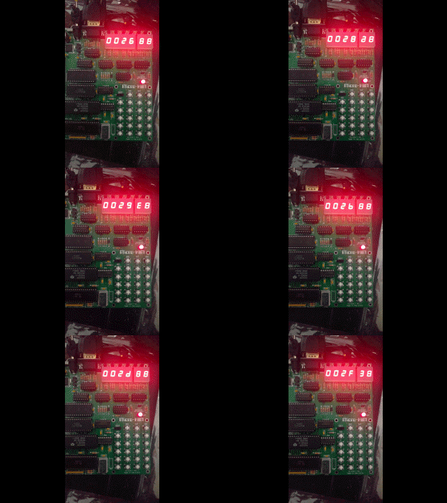
A rainy weekend was a perfect excuse to play with my micro-KIM, which had been collecting dust in a drawer for too long. I had fun using my own cross-assembler to develop and generate programs in paper tape format, and upload these to the micro-KIM via the PuTTY client. I figured out how to use the 6532 RIOT to set up a timer-based interrupt service, which is an important step in separating actual computation from display and keypad handling. The following clip shows the difference between incrementing a three-byte memory counter at roughly 1000 times per second (timer delayed) and 100,000 times per second (full speed with about 10 cycles per iteration at 1MHz). Perhaps a nice illustration of how fast even those early computers were.