Micro-KIM Tutorial: The Monitor Program
A simplified memory map of the Micro-KIM is shown below. This tutorial explores the 2K EPROM, leaving a more detailed exploration of the free RAM and 6532 RIOT for later. Address space $1400 to $173f is unused in the standard Micro-KIM kit configuration.
+-----------+
| 2K EPROM |$1fff
| monitor |
| program |$1800
+-----------+
| 6532 RIOT |$17ff
| I/O, timer|
| and RAM |$1740
+-----------+
| optional |$173f
| I/O, timer|
| and RAM |$1400
+-----------+
| |$13ff
| 5K RAM |
| |$0000
+-----------+
Addresses $1800 through $1fff are taken by the 2K EPROM, which is a read-only memory area that stores the 6530-003 and 6530-002 parts of the monitor program. You can, of course, inspect all individual bytes in the address mode on the Micro-KIM kit, but I recommend reading the assembly listing of the monitor program in the appendix of the Setup and User's Manual of Briel Computers. The compact coding style found in this monitor program is quite educational, but the monitor program also provides a rich set of subroutines that can be used in your own programs.
When you press the reset key RS on the kit (RST signal), the 6502 processor jumps to the address stored in $1ffc/$1ffd, which has the hard-coded value $1c22 in ROM. This is the entry labeled RST in the monitor program, i.e. the KIM entry via reset. Similarly, the non-maskable interrupt (NMI signal) and interrupt request (IRQ signal) jump to addresses stored in $1ffa/$1ffb and $1ffe/$1fff, respectively, with hard-codes values $1c1c and $1c1f in ROM. These are the entries labeled NMIT and IRQT in the monitor program, which contain indirect jump instructions to the vectors NMIV and IRQV stored in RAM at addresses $17fa/$17fb and $17fe/$17ff. Since these entries in RAM are undefined on power on, the User's Manual instructs you to fill these RAM locations with the value $1c00, so that the ST key or single-step feature (NMI) or BRK instruction (IRQ) jump into the entry labeled SAVE in the monitor program.
The JP2 jumper selects whether the monitor program should handle communication over the RS232 port (jumper on) or keypad/display on the kit (jumper off). Note that both the RS232 port and keypad/display always can be programmed to work regardless of this jumper state. But the jumper is connected with bit PA0 of data port A in the 6532 RIOT, which is tested in the monitor program to decide what action to perform next.
A very useful subroutine in the monitor program labeled SCANDS appears at address $1f1f. Even though these instructions are actually part of a larger subroutine that is used to show the addresses and data during normal operation of the kit, when calling this entry directly, the kit shows the three bytes stored consecutively in zero page addresses $f9, $fa, and $fb in hexadecimal format on the 6 digit LED display.
This routine makes writing a simple three-byte counter very easy, as shown below (you can also find this source file on my Micro-KIM webpage).
scands .equ $1f1f
.org $0200
;
; Initialize a 3 byte counter to zero.
;
lda #0
sta $f9
sta $fa
sta $fb
;
; Display and increment the 3 byte counter in a loop.
; Displaying before each increment slows down counting
; quite a bit.
;
loop jsr scands
inc $f9
bne loop
inc $fa
bne loop
inc $fb
jmp loop
Using the cross-assembler as shown in the previous tutorial yields the following paper tape output.
;180200A90085F985FA85FB201F1FE6F9D0F9E6FAD0F5E6FB4C08020F22
;0000010001
Although the lower digit goes faster than the eye can see, calling the display subroutine before each increment substantially slows down counting. A follow up tutorial looks at using interrupts for display, making the actual computation, counting in this case, much faster.
That's it for now. In the next tutorial, I am going to show how to use the 6532 RIOT to take full control of the LED display, show custom-made characters at any position, control brightness, and avoid flickering. As always, like, share, or comment if you enjoy the tutorial so far.
The JP2 jumper selects whether the monitor program should handle communication over the RS232 port (jumper on) or keypad/display on the kit (jumper off). Note that both the RS232 port and keypad/display always can be programmed to work regardless of this jumper state. But the jumper is connected with bit PA0 of data port A in the 6532 RIOT, which is tested in the monitor program to decide what action to perform next.
A very useful subroutine in the monitor program labeled SCANDS appears at address $1f1f. Even though these instructions are actually part of a larger subroutine that is used to show the addresses and data during normal operation of the kit, when calling this entry directly, the kit shows the three bytes stored consecutively in zero page addresses $f9, $fa, and $fb in hexadecimal format on the 6 digit LED display.
This routine makes writing a simple three-byte counter very easy, as shown below (you can also find this source file on my Micro-KIM webpage).
scands .equ $1f1f
.org $0200
;
; Initialize a 3 byte counter to zero.
;
lda #0
sta $f9
sta $fa
sta $fb
;
; Display and increment the 3 byte counter in a loop.
; Displaying before each increment slows down counting
; quite a bit.
;
loop jsr scands
inc $f9
bne loop
inc $fa
bne loop
inc $fb
jmp loop
Using the cross-assembler as shown in the previous tutorial yields the following paper tape output.
;180200A90085F985FA85FB201F1FE6F9D0F9E6FAD0F5E6FB4C08020F22
;0000010001
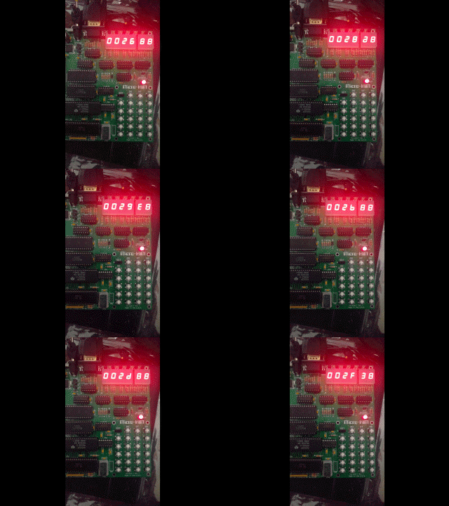
Uploading this to the kit and running looks as follows, counting up a 6 digit (three byte) hexadecimal number.
 |
| Slow counter on the Micro-KIM |


Comments